0.05 ppm/°C TCR
Bulk foil precision keeps optical power monitors and VNA calibration boards repeatable across field temperature swings.
Bulk foil resistors, NTC thermistors, ceramic capacitors, MOSFETs, and optical sensing parts help stabilize 400G line cards, PoE++ access switches, and RF calibration chains with insertion-loss budgets down to 0.15 dB.
Telecom engineers specify Vishay when the tolerance stack affects modulation error ratio, heat rise, and link margin.
| Parameter | Precision Foil Network | High-Temp NTC / MOSFET Set |
|---|---|---|
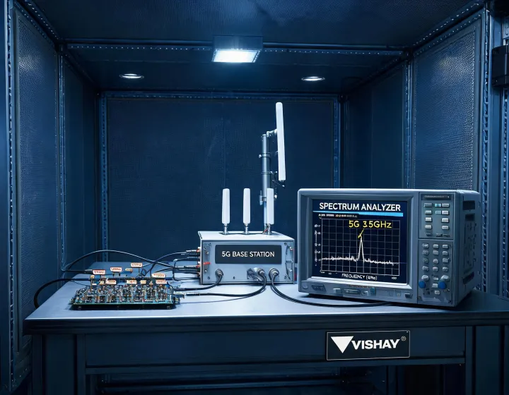
| Frequency Range | DC to 6 GHz bias and calibration paths | Sub-6 n78 radio power control |
| Insertion Loss (dB) | <0.05 dB contribution in test fixtures | <0.12 dB thermal-compensated path |
| Return Loss (dB) | Up to 26 dB with matched 50 Ω layout | 22 dB typical in protected PoE ports |
| Temperature Range | -55°C to +125°C | -40°C to +150°C junction guard band |
| Reach Impact | Protects 80 km DWDM calibration accuracy | Stabilizes 90W 802.3bt copper access |
Bulk foil precision keeps optical power monitors and VNA calibration boards repeatable across field temperature swings.
Low-noise resistor networks support RF front-end gain stability for n78 and private 5G cells.
Component tolerances are mapped to insertion-loss, return-loss, and jitter budgets before release.
MOSFET and thermistor sets help 802.3bt ports manage thermal rise in dense access switch panels.
Capacitors and inductors are selected for high ripple current in QSFP-DD and coherent transport shelves.
Application engineers review PCB keepouts, shielding, and grounding to improve >90 dB EMI control.
Send target throughput, reach, connector preference, and compliance region. A RF/optical engineer will return a component shortlist and loss-budget notes.